Retrofitting a Laser to an LPKF PCB Milling Machine
Published 23 September 2022
This article describes how I retrofitted a diode laser engraving module to an LPKF ProMat 91s/VS PCB milling machine, primarily for making solder-paste stencils and for simple engraving work.
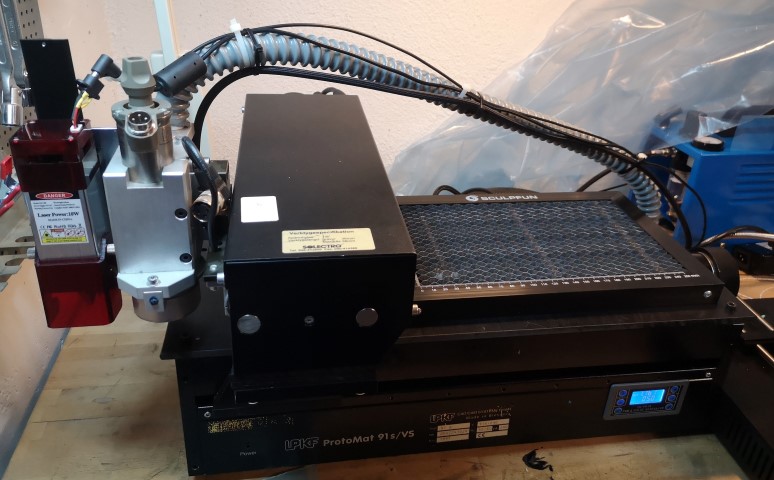
Background
I got this machine from a customer who was going to throw it away. It was old, it did not work and nobody was using it anymore. Since the mechanics were still functional, I decided to repair it as a side project and see what it could be used for.
Eventually I decided to fit a laser engraving module to it. One of the main objectives was to be able to cut simple solder-paste stencils for prototype PCB projects.
Parts and software
I am no longer certain where I originally obtained all the LPKF software. I think I found some of it on the Internet, although some may have been supplied on a disk with the machine.
I downloaded CircuitCAM as a trial version, but since it is primarily used for PCB milling I did not actually need it for the laser conversion.
For my setup I used:
- EAGLE PCB layout editor (I used version 5.9.0) and its CAM processor to generate HPGL files
- BoardMaster 3 to control the LPKF machine
- USB-to-serial converter, for example ATEN UC232A
- Diode laser engraving module with air-assist nozzle
- M5 to 1/8-inch male-to-male adapter for connecting the air hose to the nozzle
- Small airbrush compressor, such as the Biltema MC-90
- PWM generator, such as the ZK-PP1K
- A home-built delay, pull-up/pull-down and level-translation circuit using a 74HCT00, transistor, resistors and capacitors
- 12 V power supply for the laser module
- Aluminium adapter plate for mounting the laser module to the milling head
- Sacrificial wood sheets beneath material being engraved, to reduce reflected laser light
- Plastic plate to replace the aluminium worktop
- Plastic spacers to increase the available head height
- Honeycomb cutting bed, such as a Sculpfun laser honeycomb plate
Parts that need to be fabricated
- Adapter plate for mounting the laser module
- Delay and level-translation circuit
- Adapter for the 9-pin end of the USB-to-serial converter
- Plastic replacement worktop
- Plastic spacers to increase the head height
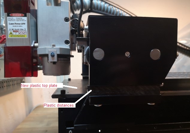
Top plate and spacers cut from the same material.
Repairing and connecting the machine
In my case I first had to replace some power-supply capacitors inside the machine.
I then made an adapter between the LPKF's 25-pin serial connector and the 9-pin serial connector on the USB-to-serial adapter.
LPKF serial pinout
Pinout from plotter (PC side):

1   PG
3   RX output
2   TX input
4   RTS input
5   CTS output
7   GND
8   DCD output
20  DTR input
The adapter was wired as follows:
25-pin      9-pin female

3     ->    2    RX
2     ->    3    TX
4     ->    7    RTS
5     ->    8    CTS
7     ->    5    GND
8     ->    1    DCD
20    ->    4    DTR
I found that the FIFO should be disabled in the advanced device settings for the USB-to-serial converter.
Starting BoardMaster
- Switch on the LPKF and wait for it to find its home position. Be prepared to switch it off if the head attempts to move into an obstruction.
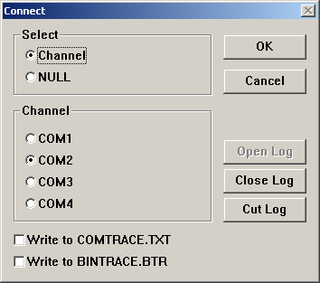
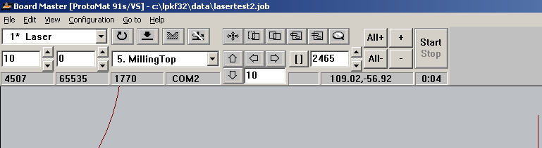
- Start BoardMaster and connect to the machine using Configuration → Connect, if this has not already been configured.
- Check the communication and machine settings.
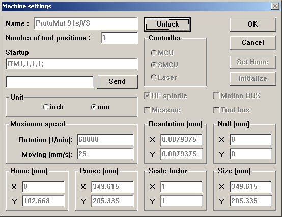
- Select View → Machine.
- Select the head-movement tool in the toolbar — the button with four small arrows — and click somewhere in the work area. The machine should move the head to that position.
Blocking the milling head
When using the laser I do not want the drill/milling head to move down or interfere with the work.
I unplugged the spindle motor and inserted a small M6 screw to prevent the milling head from being lowered by its solenoid. I would also have disconnected the solenoid itself, but it did not have a convenient connector.
BoardMaster still requires me to "start the motor", including its approximately three-minute warm-up period. This is annoying since the milling motor is not actually used, but I have not found a way around it.
PWM gating and delay
In normal milling operation the milling head needs some time to move from the PU (Pen Up) position to the PD (Pen Down) position.
When the PU/PD signal is instead used to control the laser, BoardMaster stops the plotter briefly after issuing the PD command before it begins moving. If the laser turns on immediately, it burns a small dot into the material at the beginning of each movement.
The solution is to introduce a short delay between the PD signal and switching on the laser.
Delay circuit
The circuit I built used:
- Blue LED
- 49.9 Ω, 330 Ω, 22 kΩ and 47 kΩ resistors
- 100 kΩ trim potentiometer
- 10 µF capacitor
- 100 nF capacitor
- 74HCT00
- Wires, pin headers and a female BNC connector
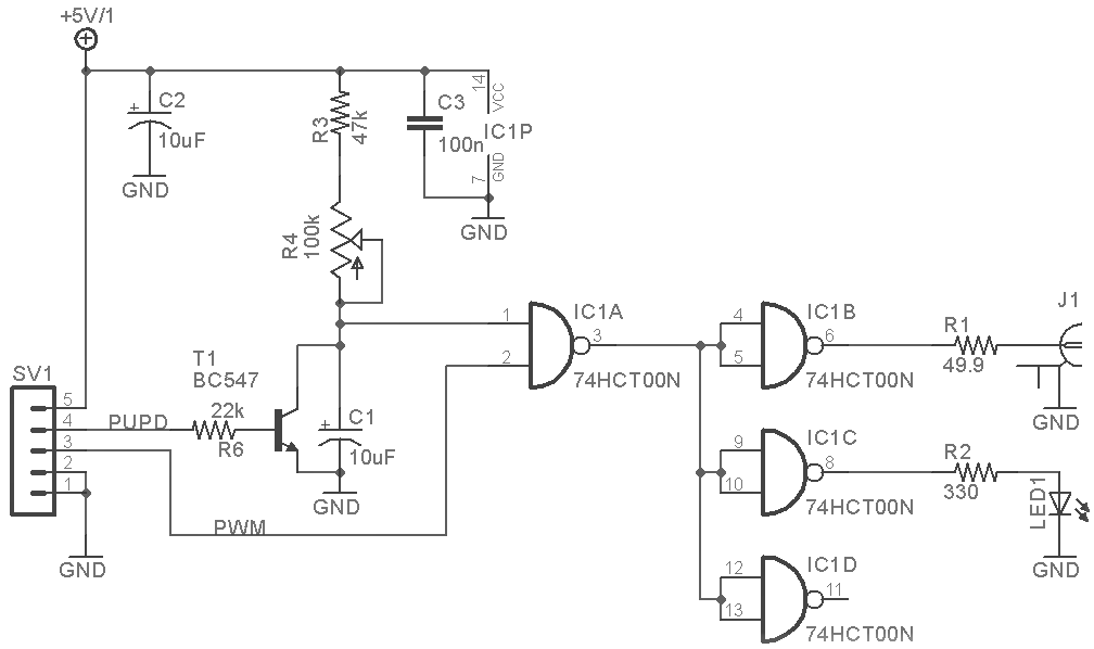
J1 is a BNC connector for the cable to the laser module's PWM input.
I encountered a troublesome ground loop involving the laser module's electronics, its PWM input and the frame of the heatsink. In my setup I therefore had to isolate the heatsink from signal ground.
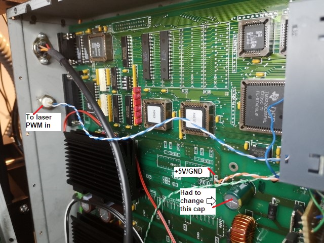
The PU/PD signal, +5 V and GND can be found inside the LPKF machine as shown below. Opening the machine requires removing all of the small screws — apparently LPKF had a particularly good price on screws — as well as the rubber feet.

The ZK-PP1K PWM generator has screw terminals for +5 V
(V+), GND (V-) and PWM.
PWM settings
The settings that worked for my particular laser were approximately:
- Cutting a thin plastic sheet using the honeycomb bed and air assist: 1700 Hz, 50% duty cycle
- Engraving wood: approximately 20% duty cycle
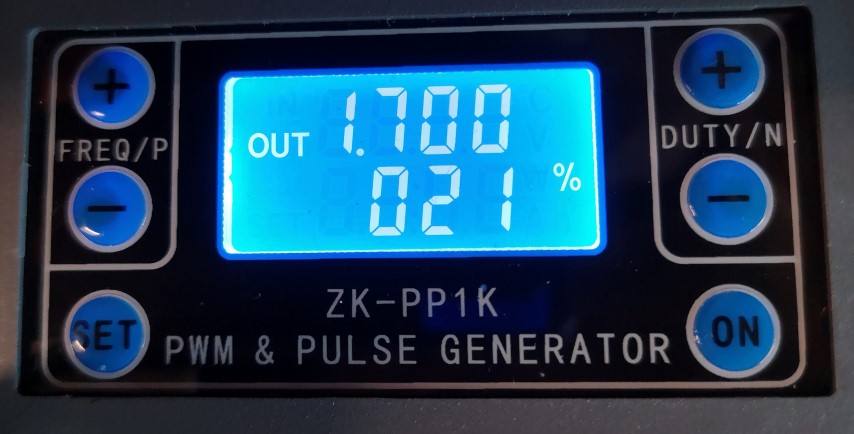
These values are specific to the laser module and materials I used. Different laser modules may require very different settings.
Preparing a job in EAGLE
Generating the HPGL file
- Start EAGLE and load the PCB.
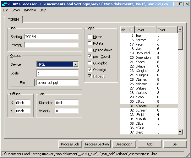
- Start the CAM Processor and load the CAM job. Select the TCREAM section and use HPGL as the output device.
- Set scale to 1 and the other relevant parameters to 0. Select Pos coord and Optimize, and select layer 31.
- Press Process Job. The HPGL file is created in the project directory.
-
Move the HPGL file to
C:\LPKF32\DATA.
Importing HPGL into BoardMaster
-
Select
File → Import → HPGL into → New LPR.
Give the LPR file a name such as
lasertest. -
Select the HPGL file, for example
tcream.hpgl. BoardMaster will normally display a warning about tool assignments. - Select Edit → Tool Assignment.... Select Phase 5 Milling Top and a milling tool. I defined a separate tool called Laser.
- In the toolbar, set Current Phase to Phase 5 Milling Top. The imported geometry should now appear in the work area.
Positioning the laser
- Right-click inside the loaded job. Adjust the Origin X and Y parameters to position the job on the work area.
- Select the head-movement tool — the button with four small arrows — and click on several points in the job. Verify that the laser head moves to the expected positions.
- Readjust the job origin if necessary.
Starting the job
- First move the head once using the toolbar's four-arrow movement button. On my machine the job does not start correctly if this step is omitted.
- Start the spindle using the button with the crossed/bent arrow. BoardMaster performs a roughly three-minute motor warm-up. Although the milling motor itself is disconnected, this step is necessary for the PU/PD functions to operate.
- Switch on the laser and air compressor.
- Select the area to cut or engrave using the selection tool to the left of the magnifying-glass button. The selected geometry becomes white.
- Press the + button. The selected geometry is added to the job and becomes red.
- Press Start. The head moves to the tool-exchange position and BoardMaster asks for the required tool.
- Start the engraving/cutting operation.
I occasionally get a buffer overrun on complex jobs, so I normally supervise the machine while it is operating. I suspect this is related to timing through the USB-to-serial adapter, but I have not found a definitive solution.
Curiously, having Task Manager running — or otherwise slightly slowing down the computer — seems to reduce the problem.
Engraving wood
A4-sized thin wood sheets intended for laser engraving are readily available. Using air assist produced the result shown below.
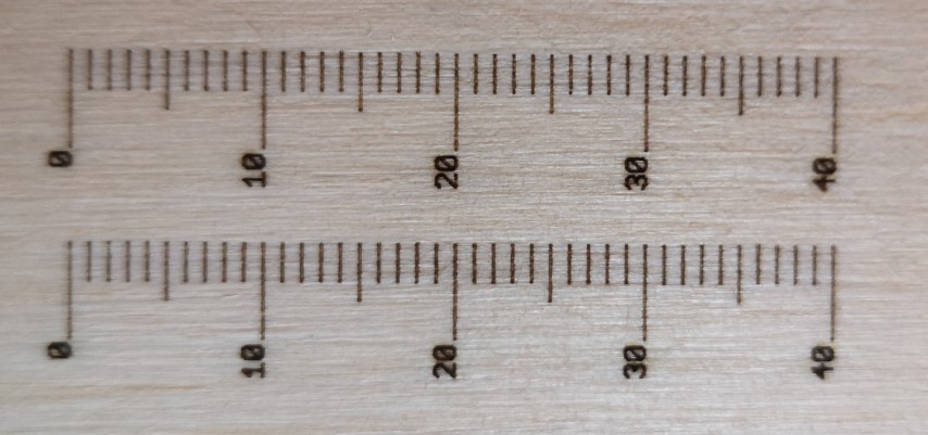
Engraving test. The bottom ruler was engraved without air assist.
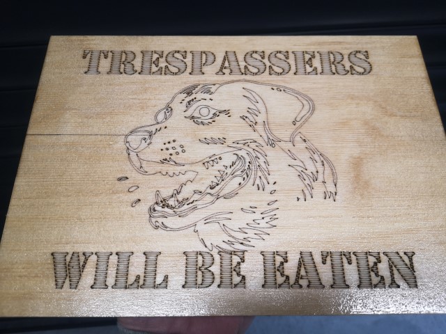
The machine can also be used to engrave signs. The example below was created in Inkscape and exported as HPGL.
To generate the filled/hatch pattern for the text I used the AxiDraw extension .
Cutting a solder-paste stencil
For prototype solder-paste stencils I use a thin semi-transparent sheet material that appears to be some form of plastic/paper composite.
When generating HPGL from EAGLE I noticed that rounded rectangles in the TCREAM layer are filled by the HPGL output. This causes the laser to spend considerably more time cutting each aperture.
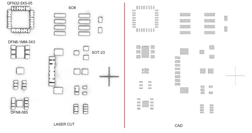
Another problem is the laser kerf. The beam removes material from both sides of the nominal aperture boundary, so narrow strips between adjacent pads can become too thin and break.
EAGLE provides a way to shrink the cream-mask apertures using the cream settings in the DRC dialog:
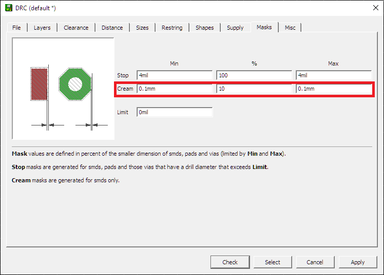
With the settings shown above, I obtained the following result:
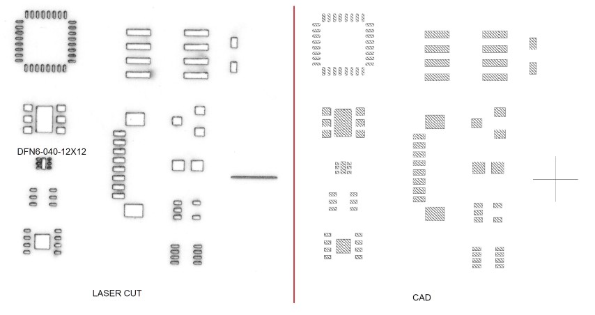
This stencil was actually usable. The main exception was the DFN6-040-12x12 footprint, which has a pad pitch of only 400 µm. The laser beam diameter is approximately 100 µm, making geometries of that size difficult to reproduce reliably.