Off-grid Solar Inverter as UPS
Published 19 October 2023
A high-power UPS can be quite expensive. An alternative worth considering is an off-grid or hybrid solar inverter.
The problem: smoke
My old APC RM2200XL eventually went up in smoke. It was very old and needed replacement anyway, but its failure highlighted a few things I did not particularly like about the design.
- When it failed, an entire row of inverter transistors was destroyed. All of them cracked. A less dramatic failure involving a fuse would have been preferable.
- The batteries are mounted inside the UPS. This is not ideal for ventilation and makes swollen batteries particularly inconvenient to remove.
One advantage of the APC was its support by
apcupsd under Debian, making integration with the servers
through the serial interface straightforward.
Temporary solution – a low-frequency inverter
I already had an off-grid solar inverter available. It was sold as a WIPANDA I-P-XD-3000VA when I bought it and is a low-frequency 48 V inverter.
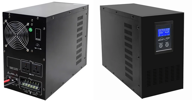
The inverter has no built-in solar charge controller. The 48 V battery bank therefore sits separately beside the inverter, which I actually prefer to having batteries enclosed inside a UPS.

My particular unit had a few quirks. When I first investigated it I discovered that the cooling fans had been connected backwards. It also occasionally reports an overload even with a relatively small load. It still works as a UPS, but today I would consider this design rather outdated.
Serial monitoring
I wrote a small Python 3 program, pups.py, to communicate
with the inverter over its serial interface. In my installation another
UPS handles the actual server shutdown, so this program was mainly used
for monitoring.
A typical status query looks like this:
MODEL: SIN3000wGERMANY Z2111D0002
STATUS: ONLINE [0x00, 0x94, 0x93, 0x64, 0x5e, 0x3a, 0x32, 0x0d]
LINEV  : 231.2
OUTPUTV: 231.1
BCHARGE: 100
LOADPCT: 94
BATVOLT: 54.9
LINEFREQ: 50
The firmware identifies itself as SIN3000wGERMANY.
The reported load percentage is clearly inaccurate on my unit;
the displayed 94% did not correspond to the actual load.
The utility communicates at 2400 baud and can query inverter state as well as send commands for self-test, alarm, shutdown, restart and calibration.
dialout group.
Next attempt – a hybrid solar inverter
Because of the irritating overload alarms I eventually bought another inverter: an EAsun ISolar-SMH-II-7KW, a high-frequency hybrid solar inverter.
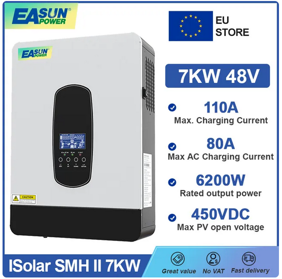
At the time it cost roughly EUR 400, considerably less than a modern commercial UPS of comparable power. The nominal inverter capacity is considerably higher than that of the old APC unit.
Unlike the earlier iPanda inverter, the EAsun also contains an MPPT solar charge controller. Our normal solar installation uses an SMA grid-tied inverter, but in an extended grid outage the MPPT input gives the possibility of connecting solar panels directly to the backup inverter.
Compared with the older inverter, advantages include:
- Lower weight due to high-frequency operation
- Higher output power
- Better graphical display
- No recurring false overload alarm
- Built-in MPPT solar charger
- Serial interface for monitoring
- Wall mounting
- A considerably better manual and menu system
Software for UPS operation
I wrote another Python program, ups-easun.py, which can
operate either as a command-line utility or as a monitoring server.
A verbose status query produces output similar to:
STATUS : BYPASS
LINEV : 231.4
LINEFREQ : 50.0
OUTPUTV : 231.4
OUTFREQ : 50.0
OUTVA : 0556 VA
OUTPWR : 0543 W
LOADPCT : 008
BUSVOLT : 427
BATVOLT : 54.00
CHRGCURR : 000 A
BCAPACITY : 100
HEATSKTEMP : 0020
PVINCURR : 0000
PVINVOLT : 000.0
The software can also run as a TCP server, create CSV battery logs, send email notifications and execute shutdown, park and unpark scripts at selected battery voltage levels.
Downloads
Software, protocol documentation and other files related to this project are available in the EAsun ISolar SMH II 7 kW download directory .
- ups-easun.py – monitoring and UPS control for the EAsun inverter
- pups.py – simple serial monitoring utility for the older iPanda inverter
Installation
Installation was fairly straightforward. The mains input and inverter output use screw terminals, so the input and load cables have to be made separately.
To reduce fire risk I mounted the inverter on a fibre-cement board on the server-room wall. Care should also be taken to keep debris away from the ventilation openings.
I initially used the inverter with its default settings. Battery type, charging current, cut-off voltages and many other parameters can be configured from the front panel.
Electrical measurements
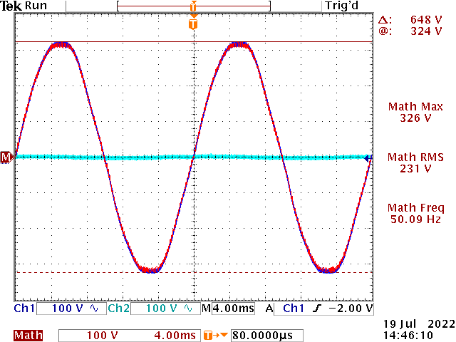
Output in bypass mode
In bypass mode the output essentially follows the mains input. The oscilloscope measurement below shows phase and neutral relative to protective earth, with the mathematical trace showing the voltage between the two output conductors.
Output in inverter mode
In inverter mode my unit behaves differently. I measured approximately 115 VAC between each output conductor and protective earth, with the two conductors approximately 180 degrees out of phase. The voltage between the two output conductors is approximately 230 VAC.
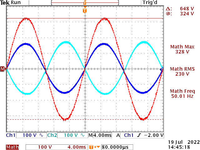
The differential waveform was very clean and, in this measurement, actually looked cleaner than the incoming mains waveform.
I have encountered a similar arrangement in military field generators. When working with field hospitals, we were instructed that, in an emergency, certain 115 VAC equipment could be operated between one output conductor and protective ground. This was a feature of those particular generator systems and should not be taken as a general recommendation for mains installations.
Transition from bypass to inverter mode
The transfer time between bypass and inverter operation can matter for some equipment. I measured the output while disconnecting the mains supply.
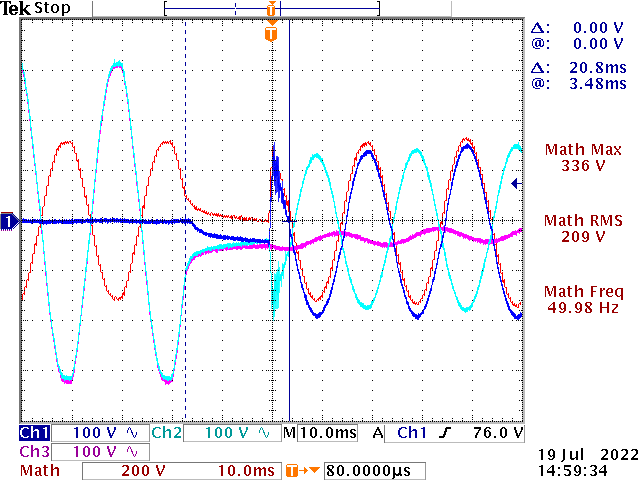
In this measurement there was a dead time of approximately 20 ms, about one 50 Hz mains period, before a good sine wave appeared on the output.
The inverter was configured in Appliance mode during this test rather than UPS mode. UPS mode may reduce the transfer time, but I have not measured it.
My loads are primarily computer switch-mode power supplies. Their mains input is rectified and buffered by relatively large capacitors, so a 20 ms interruption has not caused problems in this installation.
Battery tests
The original batteries
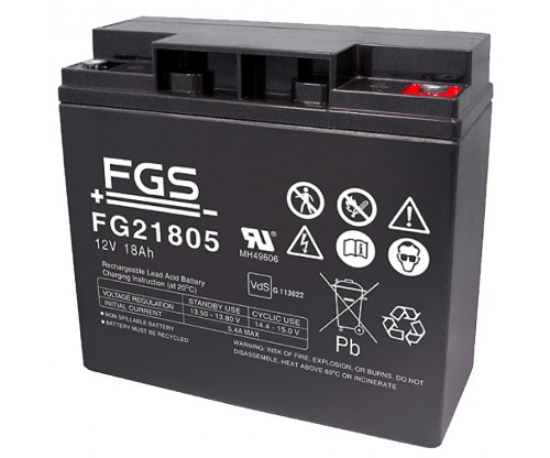
I reused the battery packs from the old RM2200XL. They consist of four 12 V, 18 Ah FG21805 batteries and were already fairly old.
I logged input voltage and frequency, output voltage, load, battery voltage, battery state of charge, charging current and heatsink temperature while disconnecting mains power for approximately 1000 seconds.
The battery voltage dropped rapidly when the inverter entered battery operation.
A rough curve fitted to the recorded battery voltage was:
v = 27.24 / (t + 8) − 0.00155 · t + 48.78
where t is time in seconds.
For longer times the reciprocal term becomes relatively small. Using the fitted curve, the estimated time to reach 46 V was only about 30 minutes. I used 46 V because this was my configured threshold for returning to mains operation when using battery-first mode.
Extending operation toward the lower 42 V cut-off gave an estimated runtime of around 73 minutes, but deep discharge at that level would considerably increase battery wear.
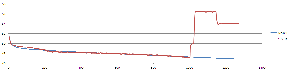
The poor result was not especially surprising: these batteries were already old and may previously have suffered deep discharge.
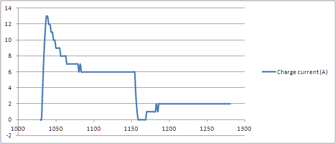
When mains power returned, charging did not start immediately. The inverter waited approximately 20 seconds and then increased charging current to a peak of about 13 A.
Adding a newer battery pack
I later connected another, newer 48 V battery pack from 2017 in parallel with the original pack.
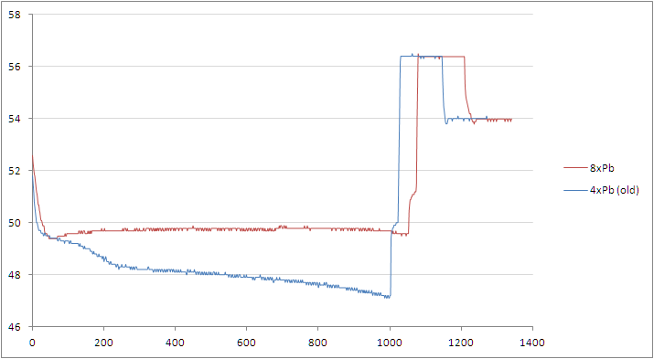
The improvement was substantial. During a roughly 1000-second test the discharge slope was much smaller even though the load had also increased.
At the end of the test the reported battery capacity was approximately 74%, compared with about 50% during the earlier test.